This site contains affiliate links, view the Disclaimer for more information.
Start with the actual board and screen, then make room for cables, sound and a back panel you can reopen.
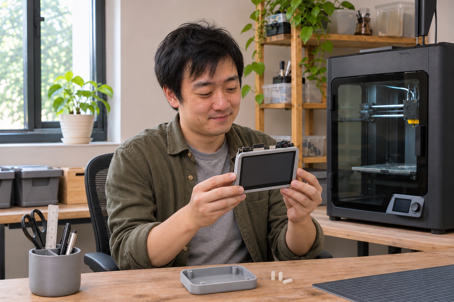
A small kitchen display is appealing until you turn it over. The screen looks neat from the front, but the board, plugs and speaker still need somewhere to go. The lid has to close without pressing on them, and the programming port needs to stay reachable when the software changes.
A useful first enclosure starts with those ordinary details. Lay out the real hardware, decide where it will sit, and print a small fit check before committing to the full shell.
Decide what the display needs to do
For a kitchen assistant, the phone or backend might manage the food inventory while the display shows a timer, a short list or a reminder. Write down which jobs belong on the device before choosing openings and mounting positions.
If the first version only shows a timer, you can plan around the screen and its controls. Voice input adds microphone access; spoken alerts add a speaker and its cable. A camera adds another opening and a clear view. An enclosure with no access to those parts can become an obstacle to the next software update.
Get the intended screen and a basic application working on the bench first. Buying an ESP32 board does not supply a kitchen-assistant application, its backend or a finished enclosure model. This guide covers the physical planning that comes next.
Write down the whole board name and revision
ESP32-S31-Korvo-1 is a specific development board. A listing for another ESP32 board is not a mechanical substitute simply because the names look similar.
Espressif documents the S31 Korvo with a 4.3-inch LCD subboard, microphones, camera, speaker connections and a microSD slot. Its revision notes distinguish the original V1.0 layout from V1.1, where the LCD stacks over a larger main board. Check the markings on the hardware you receive before borrowing a case file or copying its mounting points.
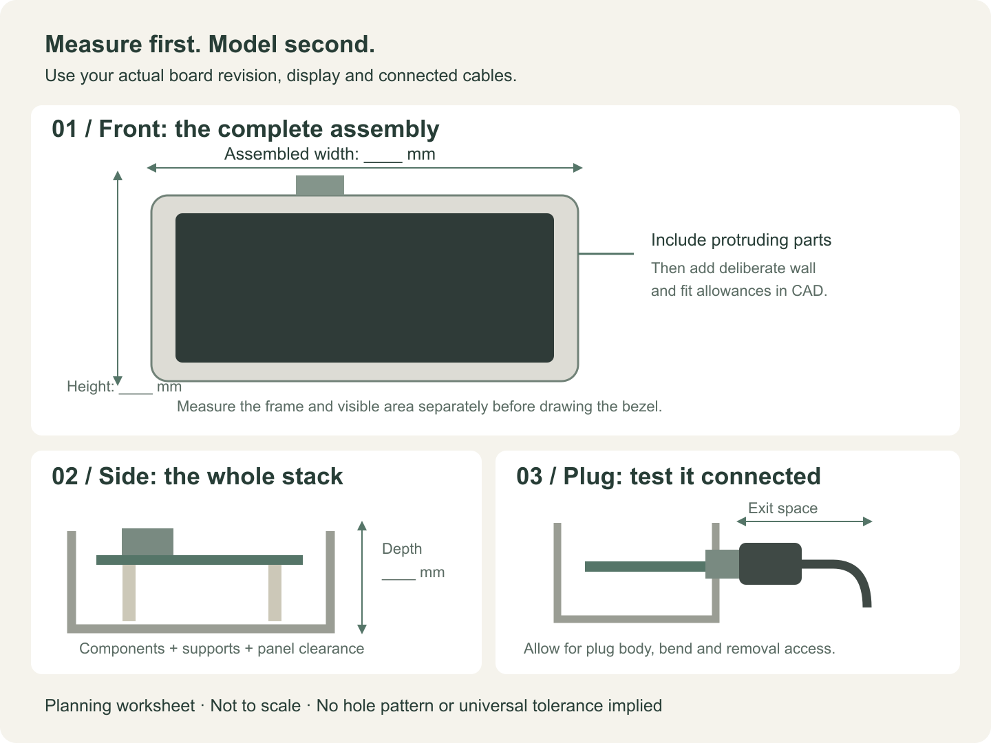
The official V1.1 PCB layout labels an outline of 106.50 × 89.20 mm, approximately 4.19 × 3.51 inches. That is a board reference, not a finished enclosure’s internal size. It does not establish the space needed by the complete screen assembly, plugged-in cables or your chosen supports.
| Record before drawing the shell | Why it matters |
|---|---|
| Board model and PCB revision | Fixes which outline and connector positions you are designing around |
| Actual assembled width and height | Includes the parts that extend beyond the bare PCB |
| Maximum depth on both sides | Leaves room for supports, components and the display |
| Screen frame and visible area | Keeps the bezel away from the image and touch area |
| Hole positions and usable screw depth | Avoids forcing the board onto the wrong supports |
| Every plug you intend to leave connected | Establishes the opening and cable exit you actually need |
When evaluating a downloaded model, look for its supported revision, hardware list, assembly notes and license. A finished-project video alone cannot tell you whether the case file fits your board or may be reused.
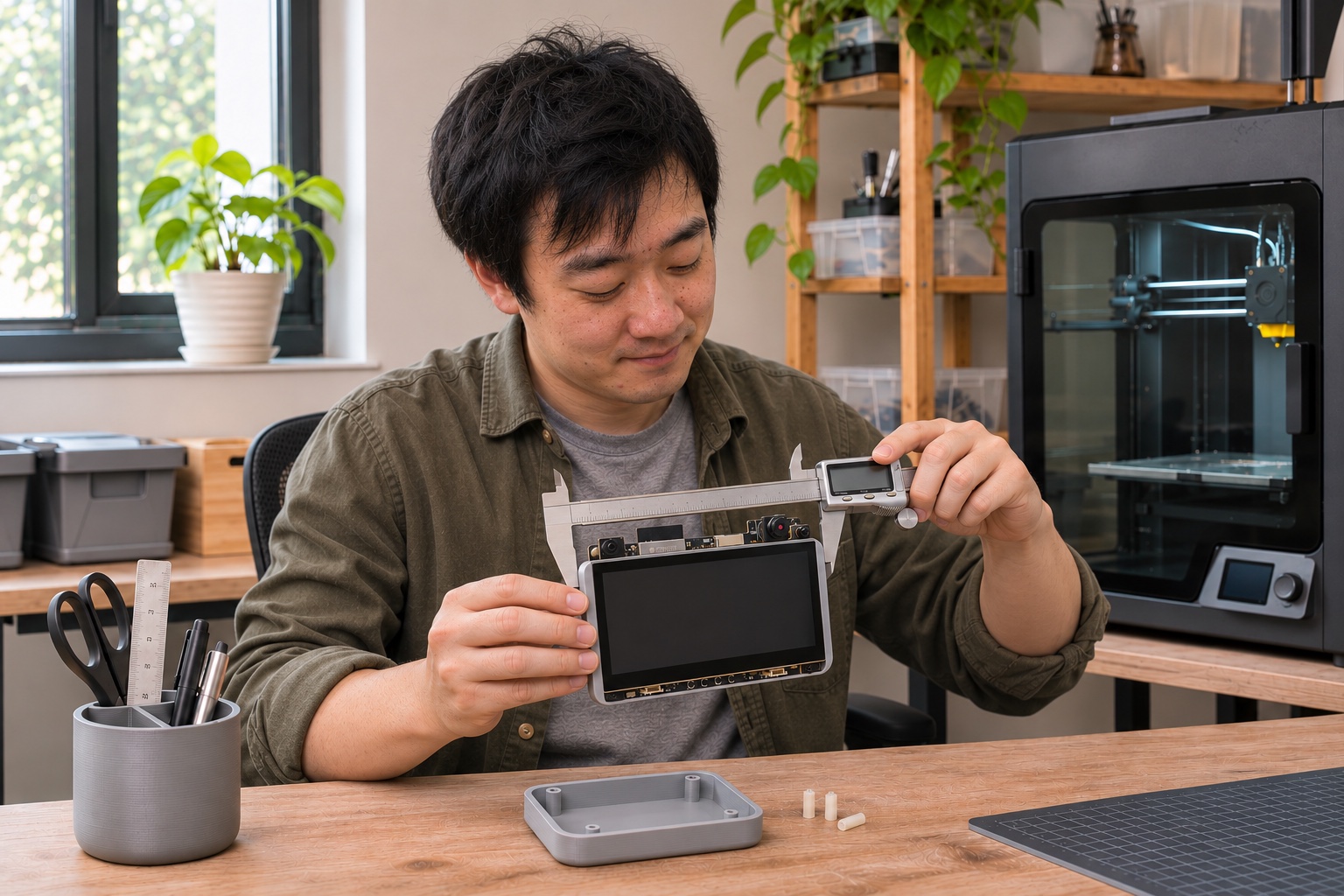
Leave room for the plugs, not just the sockets
A USB opening can look generous in CAD and still stop the cable halfway in. The plastic body around a plug can be wider than its metal connector, and the lead needs a route out of the case.
Fit the cable you plan to use while the assembly is still loose on the desk. Check its body against the wall position and try removing it without bending the board. A right-angle cable also needs checking for direction: its lead must leave toward the space you have available.
On the S31 Korvo, the power-only USB-C port and the UART USB-C port have different roles. Preserve access to the port needed for firmware work, along with any controls your development process uses. Do not assume that access to a charging socket is enough to maintain the device.
Make the rear panel removable
The back is the part you will want to reopen when a cable works loose, the speaker needs moving or a component has to come out. Plan that access before making the front look finished.
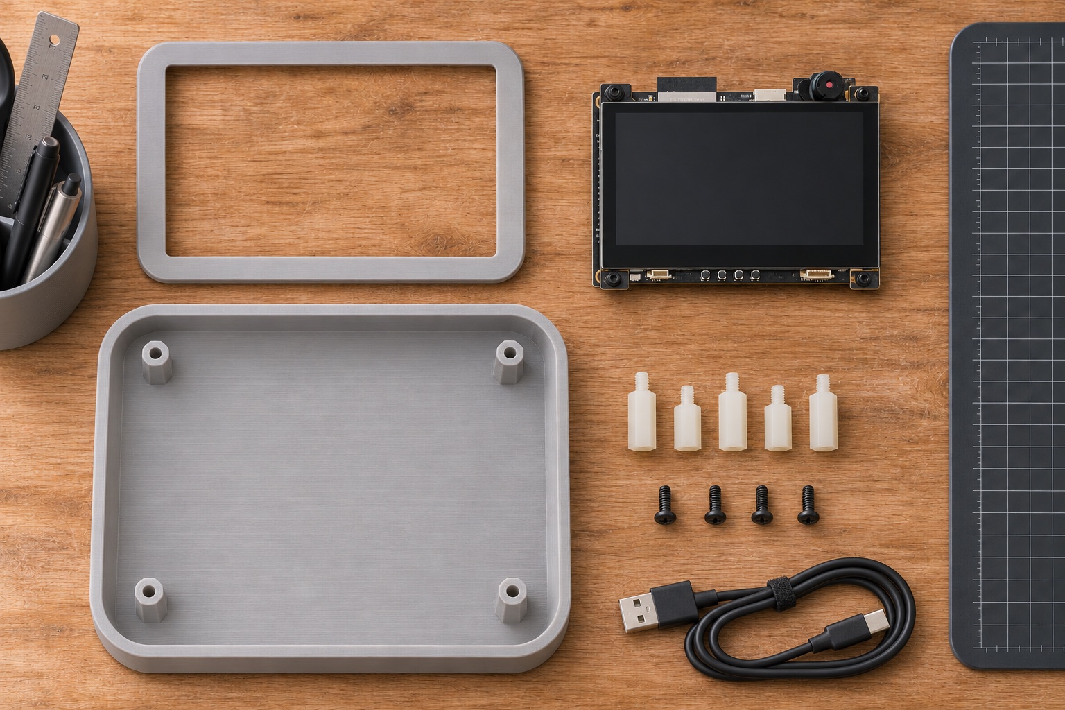
Use supports that match the actual holes and clear the components underneath. Nylon spacers are one option to compare; choose their thread, height and screw length from the hardware rather than from a photograph. A mixed M2/M2.5/M3/M4 listing is a range of choices, not proof that one size fits this board.
Place the loose supports and screws beside the board, then check that the panel can close without loading the screen, connectors or cables. Keep the speaker and its lead out of the fastening path. A plain removable back is easier to inspect than a sealed shell whose internals have not been checked.
For a voice-enabled version, plan openings around the actual microphone and speaker locations. Check the board documentation and the assembled hardware; a decorative grille in a convenient corner may not align with either.
Prove one difficult fit before printing the whole case
Choose the feature most likely to cause trouble: the USB recess, the screen corner or one support. Print a small section containing that feature and try the real part against it. Keep the test and its settings so that you know which version you checked.
If the plug catches, adjust the opening or wall position. If the board rocks on its supports, inspect the support heights and underside clearance. Record the change instead of applying the same extra clearance to every part of the model.
Then make a simple front-and-back trial shell. Check assembly, cable removal, rear-panel access and the intended screen orientation before adding decorative details.
Choose the kitchen position last
Start with a dry external position where the screen is readable and the power lead does not cross a working area. Keep the electronics away from splash, steam and cooking heat. A printed enclosure should not be assumed waterproof or suitable for food contact.
A magnetic mounting idea needs its own trial with the complete device and cable. Do not infer a holding force or magnet count from a video. Check stability and wireless operation in the intended position before closing the design around that mounting method.
The first useful result is a serviceable enclosure whose parts fit, whose ports remain accessible and whose back you can reopen. Final styling can follow that fit check.
Parts and tools to compare
The following links are starting points for the board family, measuring tool and optional supports. Confirm the board revision, included display and selected fastener sizes with the seller. They are not a complete bill of materials or a confirmed FreshMate reproduction kit.
What to look for
Compare the model numbers and fit details before ordering. Product photos are from product catalogs and retailer listings.
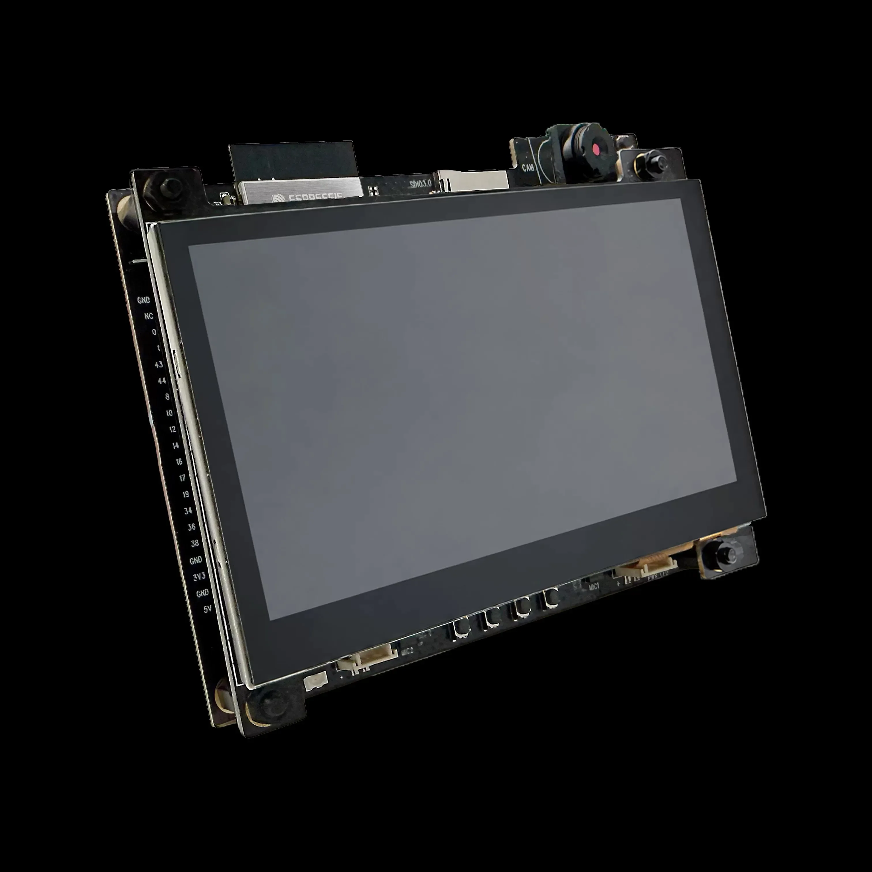
ESP32-S31-Korvo-1 development board — confirm revision and LCD
A board-family lead for a custom enclosure. Ask for the PCB revision, included 4.3-inch LCD subboard and a photo of the actual supplied assembly. Listings alone do not confirm a fit with an existing case or the source project.
View on AliExpress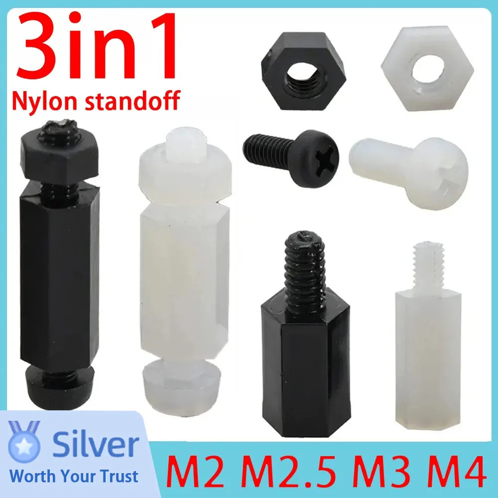
Nylon PCB spacers and screws — select the measured size
For planning removable board supports. The listing offers several thread sizes and lengths; measure the mounting hole, underside clearance and available screw depth before selecting a variant. Not a confirmed fastener set for the Korvo board.
View on AliExpress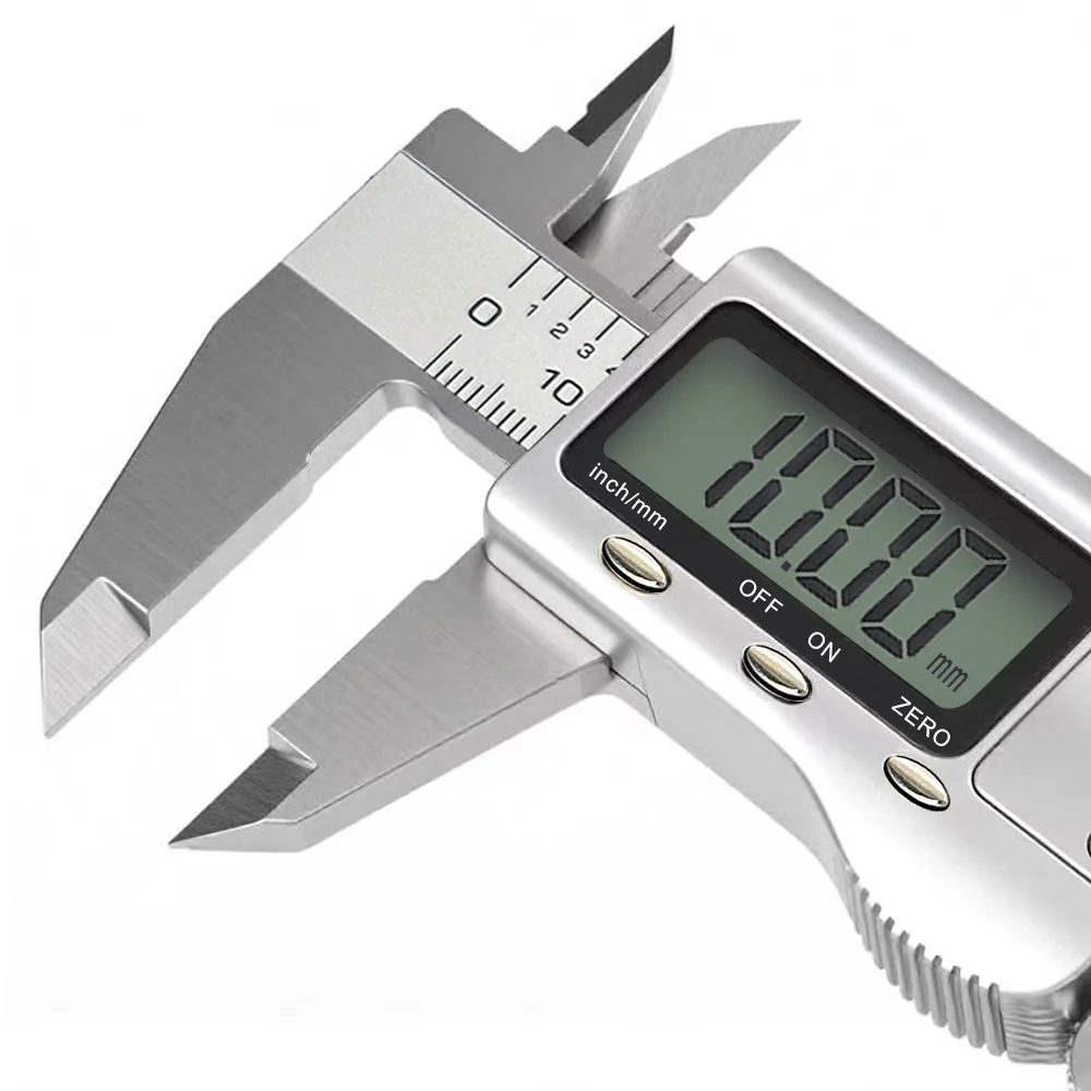
150 mm digital caliper
A measuring tool to compare for board edges, connector bodies and trial openings. Check zero and the specification of the supplied model; a digital display does not establish its measurement accuracy.
View on AliExpress